Make sure the cables used during the test meet the test system maximum voltage rating. High-voltage, low-current tests are often encountered during off-state characterization of power devices, and cables that can achieve the performance required for such tests are used.
During high voltage testing, ensure adequate insulation and minimize the effects of leakage current and system capacitance.
Rroper Insulation
Use a cable with a withstand voltage rating that is at least the maximum voltage of the test system. To achieve low current measurements, use high quality insulators in the test fixture. Insulation resistance in parallel with the DUT resistance will introduce measurement errors. With the Model 2657A Source Measure Unit (SMU), voltages up to 3kV can be present in the test circuit, so the current through these insulators is relatively large relative to the measured current through the DUT. For good measurement results, make sure that the insulation resistance is several orders of magnitude higher than the resistance of the device under test.
Leakage Current and System Capacitance
Use guards to minimize the effects of insulators in the test circuit. Guarding is a technique for forcing a low-impedance node in a circuit to be approximately equipotential with a high-impedance input terminal node. In Figure 1, even with a high-quality insulator, current leakage from the insulator still exists. This leakage can be problematic when measuring currents in the nanoamp range. Note how protection improves the measurement. The leakage current will flow out through the high resistance measurement node (HI), therefore, the leakage current is not included in the measurement.
Since the protection terminal and the high-resistance terminal are at the same potential, the protection voltage is a dangerous voltage. Therefore, use triaxial cables to arm protective circuits and protect operators from electrical shock hazards. In a triaxial cable, the high-resistance end is connected to the center conductor, the inner shield is for protection, and the outer shield is grounded.
Protection also minimizes the effects of system capacitance. System capacitance affects voltage source settling and current measurement. The test setup must allow charging of the capacitors and settling current at or below the expected device measurement noise floor. The high-impedance nature of these settings will inevitably result in long settling times. A common triaxial cable capacitance is around 40pF/ft. For a two- or three-meter cable, the capacitance is on the order of a few hundred picofarads, and the voltage settling time is tens of milliseconds, depending on the maximum current of the test setup. Placing the protection on the inner shield of the triaxial cable means that there is no voltage drop in the cable insulation. Therefore, the capacitance of this insulator does not need to be charged. Under steady state conditions, the protection voltage of the high-impedance terminal (HI) is within 4mV according to the specifications of the Model 2657A Source Measure Unit (SMU). Keithley’s Model HV-CA-554 is a triaxial high-voltage cable capable of safely transmitting signals with protection voltages up to 3280V. Keithley’s HV-CA-554 cable can meet the needs of 3kV voltage, low current measurement systems. To minimize settling time and leakage current, source measure unit (SMU) protection goes directly to the device pins. Doing so avoids the need to charge other capacitors in the system. Since the protection voltage may be as high as 3kV, it is important to ensure that the protection terminal is at a safe distance away from other conductors.
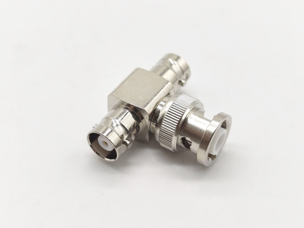
In some systems, conversion to a coaxial connection is necessary. For high voltage testing, SHV is the industry standard coaxial connector. Keithley’s SHV-CA-553 cable combination allows conversion from high voltage triaxial SHVs. These cables are combined using triaxial cables so that as much protection as possible can be implemented before connecting to the SHV. Using a coaxial connection will result in degraded performance because the benefits of protection are lost from the point of protection termination. This means that residual cable capacitance and test system capacitance must be charged.
When designing a test fixture, the user may take steps to minimize capacitance by reducing trace lengths and device connection lengths after triaxial-to-coaxial conversion.
On the probing stage, the impact of switching to coaxial connections can be even greater, where cables and connections depend on wafer size and device orientation (vertical or lateral). If the cable capacitance is taken into account, the capacitance in the probe station can easily reach nanofarads, resulting in longer capacitor charging times and measurement settling times.
Elecbee is a company specializing in the research and development, production and sales of electronic connectors, adapters and antennas. Whether it is technology, research and development, production or business, it is in the leading position in the industry. If you want to know more about our products or need related help and support, you can directly communicate with our technical staff in real time on the website or send an email to service@elecbee.com. All Elecbee staff look forward to cooperating with you.

